We are given the particulars in the circuit below in FIG. 1 and asked to calculate E2.
FIG. 1: Circuit
Having a Current Source
The voltage drop across resistor R1=600Ω is given as 80V. Thus, using Ohm’s law of I=V/R the current flowing in R1 can be calculated. The current flowing through R1 is chosen to be I2 in the circuit above.
I2 = 80V/600Ω
= 0,13A
Kirchhoff’s current law (KCL) which states:
“…total current or charge entering a junction or node is exactly
equal to the charge leaving the node as it has no other place to go except to
leave, as no charge is lost within the node.“
Using KCL and the currents chosen and indicated
in the circuit it can be said that:
I3 + I2 = I1
I3 = I1 – I2,
I2 was calculated as 0,16A and I1 is given as 3A.
= 3A-0,13A
= 2,87A
I3 = 2,87A
Kirchhoff’s voltage law (KVL) which states:
“…in any closed loop network, the total voltage around the loop
is equal to the sum of all the voltage drops within the same loop,”
Using (KVL) it can be stated that:
E2 = I3R2
+ I1R3
= (2,87A)(150Ω) + (3A)(300Ω)
= 431V + 900V
= 1 331V
Therefore E2 = 1 331V.
E1 = 80V-(I3)(R2)
E1 = 80V - (I3)(150Ω) + 1 331V
= 80V - (2,87A)(150Ω) + 1 331V
= 80V - 431V + 1 331V
= 980V
Therefore E1 = 980V.
What we will do next is implement our circuit
in LTspice and check if it is correct. Shown in FIG. 2 below is FIG. 1
implemented in LTspice.
FIG. 2: LTspice Circuit
So, we are working backwards so to speak. We have set V1 which is
our E1. We calculated it
to be = 980V so that V1=980V. We also have set V2 which
is our E2 which we
calculated to be = 1331V so that V2=1331V. Now we are going to make
measurements to see if it complies with what we were originally given.
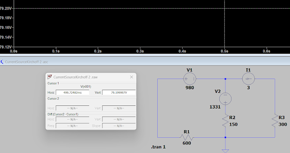
FIG. 3: Voltage Across Resistor R1 = 79.19999V
As can be seen in FIG. 3 the voltage across according to LTspice is
R1 = 79.199999V. This compares well with the 80V we were initially given. Let’s
now measure the current in R1 according to LTspice shown in FIG. 4 below.
FIG. 4: Current in Resistor R1 = 132mA.
As can be seen in FIG. 4 the
current in R4 according to LTspice is 132mA. This compares well with our
previous calculation of I2
= 80V/600Ω = 0,13A. Let’s measure the current I3
according to LTspice which is the current flowing through resistor R2.
FIG. 5: Current in Resistor R2 = 2.868A
As can be seen in FIG. 5 the current in resistor R2 according to the
LTspice simulation is 2.868A. According to FIG. 1, the current is I3.
We calculated that to be 2.87A which compares well with LTspice’s calculations.


No comments:
Post a Comment