Transient Analysis
Transients are generated in electrical circuits having energy storage elements like inductors or capacitors when sudden changes occur in the operating conditions. This occurs when the circuit is powered up for the first time. A first order circuit has a single energy storage element for example either a capacitor or an inductor. A second order circuit has two storage elements for example both an inductor and a capacitor.
R C Circuit Transient Analysis
Consider the circuit shown in FIG. 1 below:
FIG. 1: Circuit with Series Resistor and Capacitor
Using to Kirchhoff's Voltage Law (KVL) which states the voltage around a loop equals the sum of
every voltage drop in the same loop. Referring to FIG. 1 it can be said:
V = VR(t) + Vc(t)...........equation (1)
For a capacitor:
Vc(t) = 1/C∫i(t)dt or
dVc(t)/dt = 1/C i(t)
1/C i(t) = dVc(t)/dt
i(t) = C(dVc(t)/dt)..........equation (2)
In this circuit the current that flows through capacitor C also flows through resistor R.
So VR(t) = R i(t) or
VR(t) = RC(dVc(t)/dt)
Equation (1) can be rewritten as:
V = RC(dVc(t)/dt) + Vc(t)
RC(dVc(t)/dt) = V – Vc(t)
RC dVc(t) = (V – Vc(t))dt
RC dVc(t)/(V – Vc(t)) = dt
-RC ln (V – Vc(t)) = t + k.......equation (3)
To determine k a starting condition must be considered. Initially the switch is open and the voltage across the capacitor is zero. Thus at t=0, Vc(t)=0. Replacing these values in equation (3) it can be said that:
-RC ln V = k or
k = -RC ln V............equation (4)
Now substitute the value of k in equation (4) in equation (3):
-RC ln (V – Vc(t)) = t -RC ln V
-RC ln (V – Vc(t)) + RC ln V = t
-RC ((ln (V – Vc(t)) - ln V) = t
ln (V – Vc(t)) – ln V = -t/RC
ln ((V – Vc(t))/V) = -t/RC
Taking the anti-log on both sides
(V – Vc(t))/V = EXP(-t/RC)
V – Vc(t) = V(EXP(-t/RC))
– Vc(t) = V(EXP(-t/RC) – V
Vc(t) = V – V(EXP(-t/RC)
Vc(t) = V(1 – EXP(-t/RC))............equation (5)
Equation (5) is the voltage across the capacitor in relation to time.
From equation (1) that is V = VR(t) + Vc(t) it can be said that:
VR(t) = V – Vc(t)................equation (6)
From equation (5) that is Vc(t) = V(1 – EXP(-t/RC)) or Vc(t) = V – V(EXP(-t/RC))
Equation (6) can be re-written as:
VR(t) = V – V + V(EXP(-t/RC))
VR(t) = V(EXP(-t/RC))..................equation (7)
The current i(t) can be written as:
i(t) = (VR(t))/R
But VR(t) = V(EXP(-t/RC))
i(t) = (V(EXP(-t/RC)))/R
i(t) = (V/R)EXP(-t/RC).............equation (8)
The RC time constant, also called tau or τ, the time constant (in seconds) of an RC circuit, is equal to the product of the circuit resistance (in ohms) and the circuit capacitance (in farads).
τ =RC (seconds)
So after one time constant τ = 1xRC = RC
Vc(RC) = V(1 – EXP(-RC/RC)) = V(1 – EXP(-1)) = V (1 – 0.3679) = V(0.6321) = 0.6321V
VR(RC) = V(EXP(-RC/RC)) = V(EXP(-1) = V(0.3679) = 0.3679V
i(RC) = (V/R)EXP(-t/RC) = (V/R)EXP(-RC/RC) = (V/R)EXP(-1) = (V/R)(0.3679) = 0.3679(V/R).
After five time constants τ = 5xRC = 5RC
Vc(5RC) = V(1 – EXP(-5RC/RC)) = V(1 – EXP(-5)) = V (1 – 0.0067) = V(0.9933) = 0.9933V
VR(5RC) = V(EXP(-5RC/RC)) = V(EXP(-5)) = V(0.0067) = 0.0067V
i(5RC) = (V/R)EXP(-t/RC) = (V/R)EXP(-5RC/RC) = (V/R)EXP(-5) = (V/R)(0.0067) = 0.0067(V/R).
FIG. 2: VC(t) and VR(t) as a Function of Time in Time Constants
Shown below is the circuit current i(t) as a function of time in time constants.
FIG. 3: I(t) as a Function of Time in Time Constants
FIG. 5: Traces Input Voltage-Red, R1-Green, and C1-Blue Simulated in LTspice.
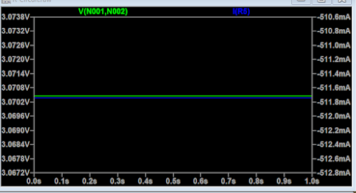
Shown in FIG. 6 below is the input voltage indicate by the blue trace and the current in R1 is shown by the green trace.
FIG. 6: Traces Input Voltage-Blue and R1 Current-Green Simulated in LTspice.
There is some resemblance between the resistor calculated voltage and current and capacitor voltage and that of the values obtained by the LTspice simulation.


